Name the condition first
A sensor should be selected against a defined condition: displaced geometry, an exposed surface discontinuity, loss of section, debris or a change in seabed level. These conditions do not share a single best observation method. A camera may reveal a surface feature but cannot establish remaining wall thickness from appearance alone. Acoustic geometry may reveal a large obstruction while leaving a fine crack unresolved. An ultrasonic reading can quantify a local thickness without describing the surrounding surface comprehensively.
Specify the expected feature size, orientation and material, together with access and surface condition. Distinguish detection from characterisation and sizing. Seeing that something is unusual may justify a closer examination without supporting a repair decision. Detection performance should be demonstrated under representative conditions; it cannot be inferred solely from the smallest increment shown in a software display.
Optical methods need controlled geometry
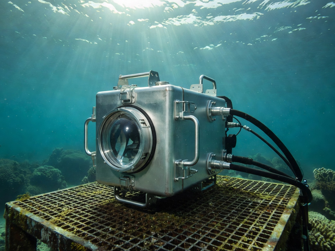
Underwater cameras can support visual assessment, dimensional estimation and photogrammetric reconstruction. Their usefulness depends on lighting, focus, range, viewing angle and water clarity. Backscatter from suspended particles may dominate a brightly lit image, while marine growth can hide the actual substrate. Changing the lighting geometry can improve visibility, but it does not reveal material beneath an opaque covering. Record the limitation rather than interpreting the covering as the underlying surface.
Laser scaling or calibrated stereo arrangements can help measure visible features when the required geometry is satisfied. A pair of laser dots does not guarantee valid scale for every orientation or uneven surface. Refraction through a camera port and changes in camera configuration affect calibration. Photogrammetry needs suitable overlap and stable features; a detailed mesh can contain registration errors or interpolated surfaces. Retain the original images and validation information alongside derived models.
Acoustic methods reveal different geometry
Imaging sonar is valuable when visibility is poor. It can support obstacle awareness, structure-relative manoeuvring and examination of larger geometric features. However, an acoustic image is formed from reflections and shadows, not from visible surface colour. Incidence angle, range, beam geometry and material response affect what appears. A dark region might be an acoustic shadow rather than missing material. Multiple viewing angles can help test competing explanations.
Multibeam echo sounders can produce spatial measurements useful for scour assessment, seabed mapping and some structural geometry. Their uncertainty depends on sound speed, positioning, attitude, timing and installation calibration as well as the acoustic instrument. Higher operating frequency may offer finer detail in some configurations, usually with trade-offs in usable range and environmental sensitivity. Compare achieved results for the planned geometry instead of choosing from frequency alone.
Contact measurements need a procedure
Ultrasonic thickness testing can support local remaining-wall measurements when material, coupling, surface condition and geometry are suitable. It generally requires controlled probe placement and an appropriate procedure. Coatings, corrosion, curvature and roughness can complicate interpretation. Autonomous placement does not remove these requirements. A plausible numeric output is not sufficient evidence of a valid back-wall response or a representative measurement location.
ISO 16809 addresses ultrasonic thickness measurement, while ISO 9712 concerns qualification and certification of nondestructive testing personnel within its scope. Neither means every robot-mounted probe is automatically qualified for a particular asset. ISO 13628-8 addresses remotely operated vehicle interfaces on subsea production systems; it is relevant to interface design, not a general guarantee of inspection quality. Confirm current editions, applicability and project-specific acceptance requirements.
Compare the evidence, not the marketing category
| Method | Useful observation | Important limit |
|---|---|---|
| Optical camera | Visible surface condition and contextual detail | Turbidity, fouling, lighting and unvalidated scale |
| Imaging sonar | Acoustic shape, obstacles and larger features | Shadow ambiguity and geometry-dependent resolution |
| Multibeam | Spatial geometry and seabed change | Installation, positioning and sound-speed uncertainty |
| Ultrasonic probe | Local material thickness under a suitable procedure | Coupling, surface preparation and limited spatial sampling |
Build corroboration into the plan
Complementary sensors can reduce ambiguity when their limitations differ. Sonar may locate a feature for optical examination; a camera may document probe placement for a thickness measurement. But two measurements sharing the same navigation error are not fully independent confirmation. Record the relationship between datasets, including timing offsets and sensor mounting transformations, so reviewers can judge what corroboration really adds.
Finally, test the entire chain in a representative area: sensor, mounting, vehicle motion, processing and review. Include known or independently measured features where feasible. Preserve failed and ambiguous observations, not only attractive outputs. A method that reliably identifies its own unusable data can be more valuable than one that produces a seamless display without exposing uncertainty.